Consider the second-order system given by:
G(s) =1 / ((s+p1)(s+p2)) p1 > 0, p2 > 0
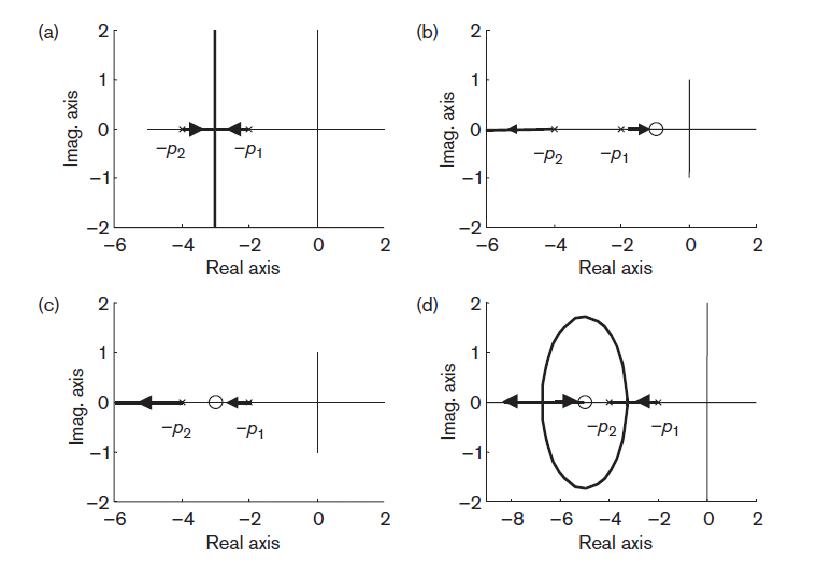
The poles are given by s = –p1 and s = –p2 and the simple root locus plot for this system is shown in Figure . When we add a zero at s = –z1 to the controller, the open-loop transfer function will change to:
G1(s) =K(s+z1) / ((s+p1)(s+p2)) , z1>0
 Effect of adding a zero to a second-order system root locus.
We can put the zero at three different positions with respect to the poles:
1. To the right of s = –p1 Figure (b)
2. Between s = –p2 and s = –p1 Figure (c)
3. To the left of s = –p2 Figure (d)
(a) The zero s = –z1 is not present.
For different values of K, the system can have two real poles or a pair of complex conjugate poles. Thus K for the system can be overdamped, critically damped or underdamped.
(b) The zero s = –z1 is located to the right of both poles, s = – p2and s = –p1.
Here, the system can have only real poles. Hence only one value for Kto make the system overdamped exists. Thus the pole–zero configuration is even more restricted than in case (a). Therefore this may not be a good location for our zero,
since the time response will become slower.
(c) The zero s = –z1 is located between s = –p2 and s = –p1.
This case provides a root locus on the real axis. The responses are therefore limited to overdamped responses. It is a slightly better location than (b), since faster responses are possible due to the dominant pole (pole nearest to jω-axis) lying further from the jω-axis than the dominant pole in (b).
(d) The zero s = –z1 is located to the left of s = –p2.
By placing the zero to the left of both poles, the vertical branches of case (a) are bent backward and one end approaches the zero and the other moves to infinity on the real axis. With this configuration, we can now change the damping ratio and the natural frequency . The closed-loop pole locations can lie further to the left than s = –p2, which will provide faster time responses. This structure therefore gives a more flexible configuration for control design. We can see that the resulting closed-loop pole positions are considerably influenced by the position of this zero. Since there is a relationship between the position of closed-loop poles and the system time domain performance, we can therefore modify the behaviour of closed-loop system by introducing appropriate zeros in the controller
No comments:
Post a Comment